
 1 of 1
- Erice
- New Member
 Offline
 - Registered: 19-8-2021
- Posts: 2
Underwood ribbon advance reversal
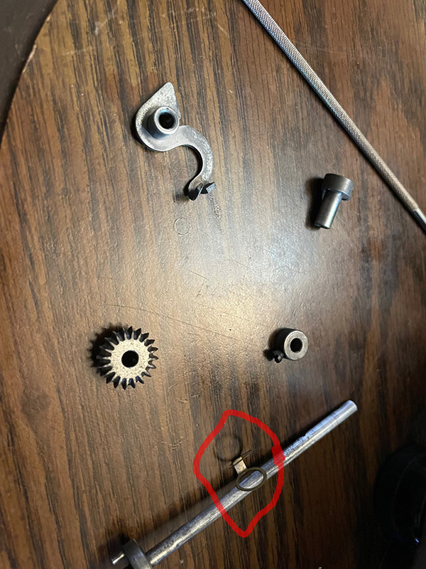
I've not been able to make the ribbon advance automatically reverse on this thing. I'm staring at the parts, and I just can't understand how it's supposed to work. I took it apart and cleaned it and put it back together, but I don't understand what the possible adjustments would accomplish to let the reverse happen. Here are a couple of pictures of what I'm looking at. I don't understand the purpose of that brass colored spring.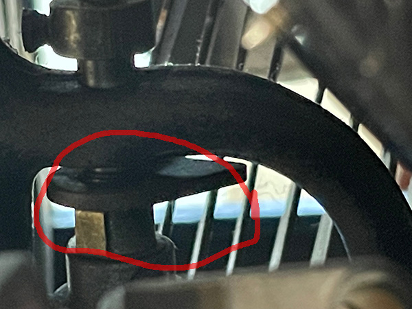
- Phil_F_NM
- Speed Champion
Offline

- From: Mid-Atlantic region
- Registered: 16-4-2020
- Posts: 267
Re: Underwood ribbon advance reversal
Which model and year of Underwood?
Phil Forrest
- Erice
- New Member
Offline
- Registered: 19-8-2021
- Posts: 2
Re: Underwood ribbon advance reversal
I don't know--why didn't any of these manufacturers have model plates on their machines?
Anyway--here are some more pics and instructions I found online, with the confusing part circled in red.
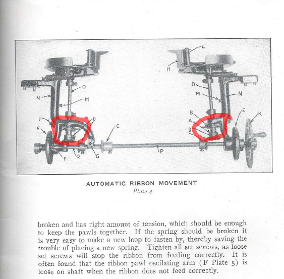
And here are some instructions I found to go with it. What's confusing me, is (using the above illustration's terminology), what makes the "ribbon shifting arm" move? I assume it has something to do with the "spool shaft spring" (the little brass colored spring) but it's not like any kind of clutch system. Possibly, it's just arranged so that the spring presses on the collar just hard enough to push it when the shifting arm is 'unlocked' but I can't make it push the arm hard enough to reverse the directions, without messing everything else up and making the whole mechanism sloppy to the point of not working in other ways.
I don't know why I'm having so much trouble understanding these mechanics--I'm usually able to tell how something works just by looking at it and toying with it for a few minutes.
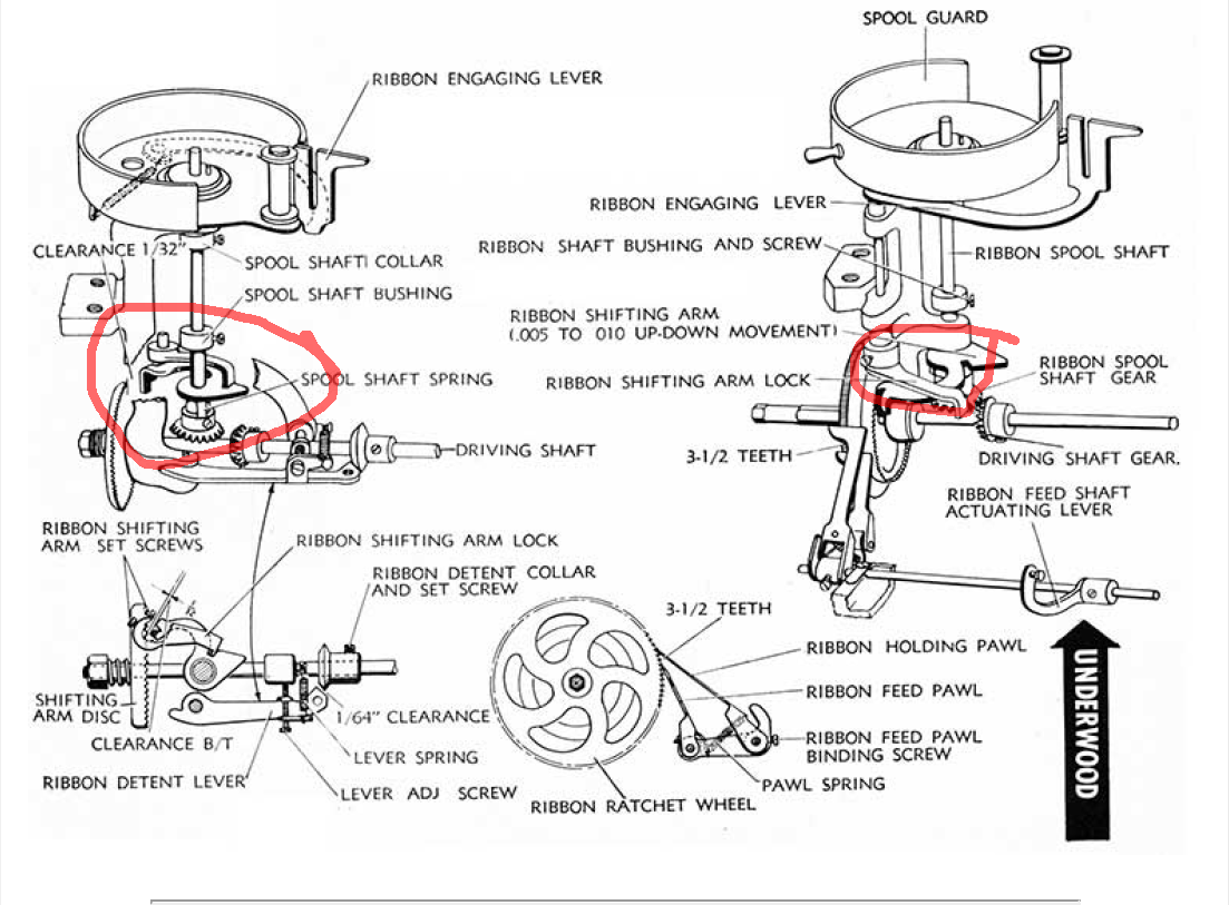
Here's part of a manual I found that has some explanation:
The Ribbon Reverse Mechanism of the Underwood is controlled by the eyelet in either end of the ribbon acting on the Ribbon Engaging Lever, moving it around to contact and place the Ribbon Shifting Arm into engagement with the Shifting Arm Disc. Pressure of the Ribbon Shifting Arm against the Shifting Arm Disc forces the disc outward moving the driving Shaft to the right or left with it. This action causes the engagement of the Driving Shaft Gear with the Ribbon Spool Shaft Gear, causing feeding of ribbon on the empty spool.
2. ADJUSTMENTS.
Before attempting Ribbon Feed Adjustment, check common causes of Ribbon Feed Trouble, Foreword sheet of this Section. Check also to determine that ribbon is positioned properly in slot of Ribbon Engaging Lever and that eyelets are located in both ends of the Ribbon.
a. Ribbon Feed:
(1) Ribbon Feed Shaft must be properly engaged in Rocker Arm Extension and there must be .010" to .020" end shake in the shaft. Adjustment is made after loosening Ribbon Feed Shaft Actuating Lever Collar Set Screw by positioning Ribbon Feed Shaft Actuating Lever. Tighten Set Screw when adjustment has been made.
(2) Ribbon Feed and Holding Pawl must be positioned properly on Ribbon Ratchet Wheel and there must be 3 1/2 teeth of the Ribbon Ratchet Wheel separating the two pawls as indicated in drawing. Adjustment may be made by loosening Ribbon Feed Pawl Binding Screw and properly positioning Ribbon Feed and Holding Pawls. Tighten Binding Screw when adjustment has been made.
(3) Ribbon Driving Shaft Gears, when set in either right or left position, must mesh properly with Ribbon Spool Shaft Gear. Adjustment may be made after loosening Driving Shaft Gear Set Screws by properly positioning Driving Shaft Gears. Tighten Set Screws after adjustment has been made.
(4) Ribbon Spool Shafts must be free on their bearings with .010" movement (up and down). Adjustment may be made after loosening Spool Shaft Collar Set Screws by positioning Spool Shaft Collar. Tighten Set Screw when adjustment has been made.
(5) Ribbon Spool Shaft Gears, located at the lower extremity of the Shafts, should be positioned flush with the lower end of the Shaft. Adjustment may be made after loosening Spool Shaft Gear Set Screws and positioning Gear properly. Tighten Set Screw when adjustment has been made.
(6) Ribbon Spool Guards (cups), which pivot on Ribbon Spool Bracket Casting for purpose of accessibility in replacing spool and threading ribbon through Ribbon Engaging Lever Slot, must be free on their bearings without unnecessary up and down play. Spool Guard Springs must be tensioned properly to return Ribbon Spool Guard (cups) to proper position. Set screws for positioning Ribbon Spool Guard Bushings in the Spool Guard are located directly below the Ribbon Spool Guard, front, in the Ribbon Spool Bracket Casting.
b. Ribbon Reverse:
(1) Ribbon Spool Shaft Springs should be adjusted, by forming, to provide sufficient tension to force Ribbon Shifting Arm Extension into teeth of the Ribbon ShiftingDisc.
(2) Ribbon Shifting Arms should be adjusted to provide .005" to .010" up-down movement as indicated in drawing. Adjust after loosening Ribbon Shaft Bushing Set Screw by positioning Ribbon Shaft Bushing. Tighten set screw when adjustment has been made.
(3) Ribbon Shifting Arm Locks, which work in conjunction with the Ribbon Engaging Lever, must work free on their bearings and must seat fully in Ribbon Shifting Arm Slots. Adjustment may be made after loosening Ribbon Shifting Arm Set Screws by positioning Ribbon Shifting Arm Locks. Tighten set screws when adjustment has been made. Clearance of 1/32" between Ribbon Shifting Arms and Shifting Arm Disc (except when reversing) should be maintained. Adjust by forming Ribbon Shifting Arms.
(4) Ribbon Detent Collars should clear Ribbon De-tent Lever by 1/64" as indicated in drawing. Adjustment may be made after loosening Ribbon Detent Collar Set Screws by properly positioning Ribbon Detent Collar. Tighten set screws when adjustment has been made.
- •
